
Many engineers blame the sensor when readings fluctuate, but in most cases the real issue is coupling alignment or mounting error.
Your torque sensor showed ±0.1% accuracy on the spec sheet. It passed every bench calibration test. Then you bolted it into the machine — and nothing makes sense anymore. You’re not alone, and you’re probably not crazy.
Absolutely! Let’s dive into a full 1200-word draft, structured with clear H2s and a few H3s for depth. I’ll keep it flowing naturally, balancing the technical expertise with a human touch. Here we go:
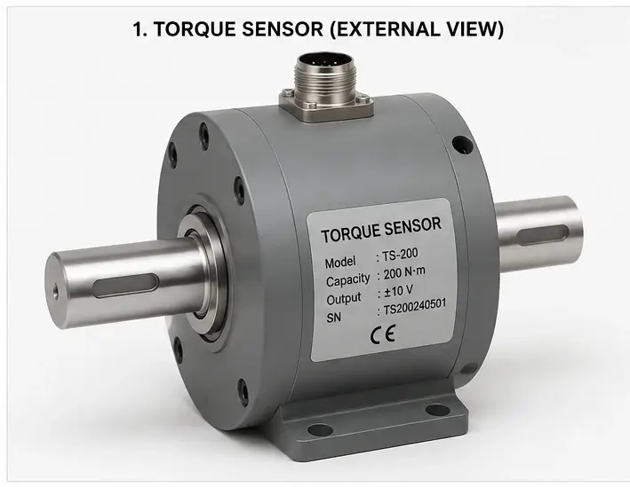
Torque sensors are the unsung heroes of industrial measurement. On the spec sheet, they promise ±0.1% accuracy—seemingly flawless. But bolt that sensor into your machine, and suddenly, numbers drift, spikes appear, and you’re left chasing a baffling gap between lab precision and production reality.
The Lab vs. The Floor: A Frustrating Discrepancy
As engineers, we trust numbers. We assume that if a torque sensor passes every bench calibration, it will perform the same way in the field. And yet, time and time again, we discover a yawning gap between the lab’s controlled environment and the factory floor’s chaos. This isn’t a flaw in the sensor; it’s a mismatch in context.
In the lab, conditions are pristine. Stable temperature, vibration isolation, and perfect alignment all conspire to produce a calibration that looks flawless on paper. But in a die-casting plant, a compressor station, or a pump line—variables like temperature shifts, mechanical misalignment, and EMI all conspire against us. And that’s where real accuracy crumbles.
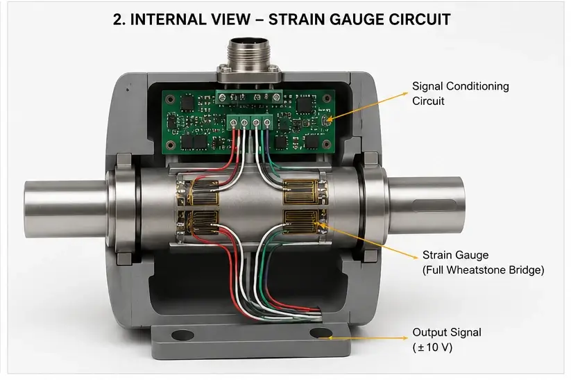
What Does Calibration Actually Guarantee?
Let’s demystify calibration. It’s a controlled process: we apply a known torque, measure the output, and create a correction table mapping input to output. But it happens in a vacuum—no vibration, no temperature swings. That correction table is only valid as long as those conditions hold. Once the real world intrudes, the sensor’s readings become approximations rather than guarantees.
The Six Silent Accuracy Killers
Now, let’s break down the six hidden failure modes. First, thermal drift: strain gauges expand or contract with temperature shifts. In a foundry, a 10-degree Celsius change can add 0.1% drift.
Second, mechanical misalignment: even a tiny angular offset introduces parasitic loads, fooling the sensor into reading false torque.
Third, electromagnetic interference: in industrial plants, motors and drives produce huge EMI that drowns out the tiny millivolt signal.
Fourth, vibration and resonance: static calibration doesn’t capture dynamic motion—so at certain speeds, you get torque ripples.
Fifth, creep and hysteresis: over time, the sensor slowly drifts under sustained load.
Sixth, signal conditioning issues: ground loops and poor excitation lead to unpredictable DC offsets.
Why Specs Fall Short for Real Industrial Use
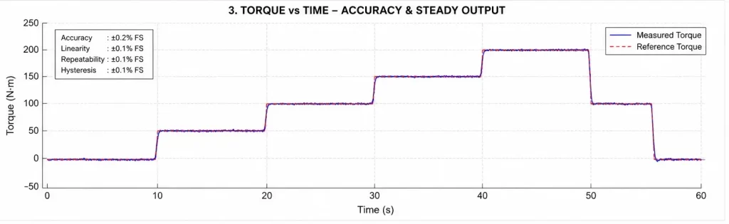
It’s not a conspiracy. Manufacturers measure torque sensor accuracy in a perfect world: fixed temperature, ideal alignment, and no EMI. But when you read “±0.1%,” it’s a combined figure of linearity, hysteresis, and repeatability measured under ideal conditions. You need to read the fine print—the temperature coefficient, EMI rating, and dynamic performance specs. The job is to ask: does this sensor really match my shop floor?
A Practical Checklist for Field Accuracy
Start at selection: match the sensor’s operating range to your real environment. Look for integrated temperature compensation—this keeps drift in check. During installation, invest in precise shaft alignment. Even a fraction off can add massive error. Route signal cables
